

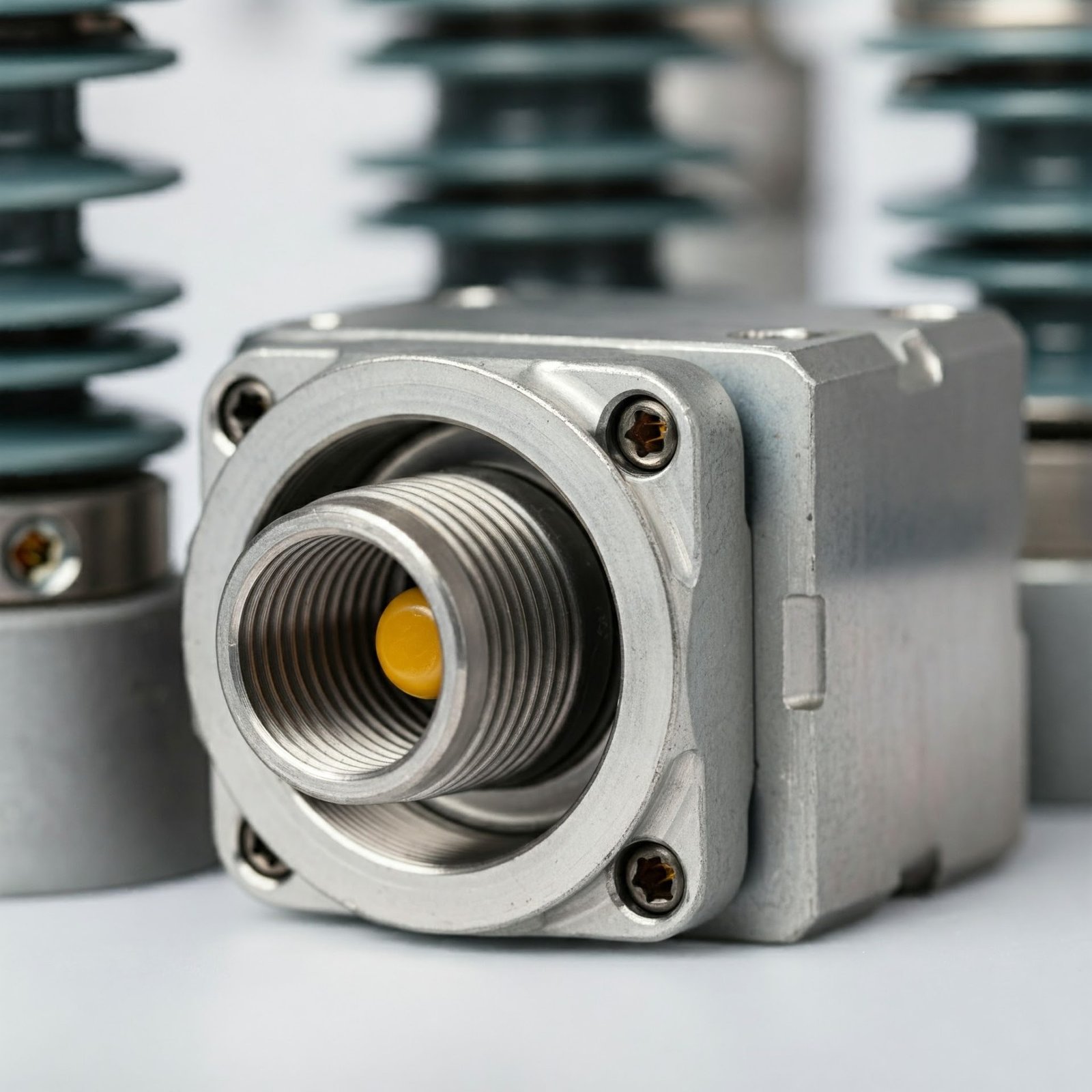
Durable and Precision-Engineered Substation Connectors of Aluminium
Our Substation Connectors of Aluminium are designed for secure and efficient connections in electrical substations, offering excellent conductivity and reliability.
High-quality Substation Connectors of Aluminium crafted for reliable and secure connections in electrical substations and power systems.
At Conex Aluminium Components, we specialize in manufacturing premium Substation Connectors of Aluminium that cater to power distribution and transmission needs. These connectors ensure optimal conductivity and mechanical stability, making them ideal for use in high-demand electrical substations. Made from corrosion-resistant aluminium, they provide reliable performance, durability, and ease of installation. Available in various sizes and configurations, our connectors meet the requirements of diverse substation applications. Conex also offers tailored solutions to match specific project demands, ensuring the highest efficiency and safety standards.
Aluminium substation connectors join busbars, tubular bus, conductors and equipment terminals in transmission and distribution yards. Typical functions include straight, tee, expansion, terminal and equipment connections. Selection depends on conductor geometry, continuous current, short-circuit forces, voltage class, mechanical loads, environment and the utility’s approved connector standard.
Connectors can be engineered for aluminium tubular bus, flat busbar, stranded conductors and compatible equipment pads. Each interface requires the correct diameter, width, thickness, bolt pattern and contact profile. Copper or dissimilar-metal interfaces require an approved bimetallic transition rather than direct contact with a standard aluminium connector.
Current capability depends on aluminium grade, cross-sectional area, contact surface, joint resistance, bolt preload, ambient temperature, solar heating and permitted temperature rise. The connector should not become the thermal bottleneck of the bus system. Continuous, emergency and fault-current duties must be supplied so electrical and thermal performance can be evaluated.
Low and stable resistance minimises power loss and local heating at the joint. It depends on contact area, surface preparation, flatness, oxide control, hardware and maintained pressure. Poor alignment, contamination or incorrect torque can create hot spots. Project qualification may therefore include resistance and temperature-rise measurements before and after thermal cycling.
Installation should follow the utility-approved procedure. Aluminium contact zones are generally cleaned to remove contamination and non-conductive oxide without damaging the surface, then protected with an approved joint compound where specified. Prepared surfaces should be kept clean, correctly aligned and assembled promptly using compatible tools and hardware.
Use the connector drawing or approved installation specification for the exact bolt size, material, washer system, thread condition and lubricant. Generic torque values can under-compress contacts or overstress aluminium threads and bodies. Tightening should follow the specified sequence with calibrated tools so pressure is distributed evenly across the electrical interface.
Fault current produces high electrodynamic forces in buswork and connections. Connector geometry, section thickness, bolt pattern, support spacing and bus arrangement must resist the specified peak and short-time currents without slipping or permanent deformation. Fault duty and structural reactions should be included in the design inputs, not inferred from continuous current alone.
Expansion connectors or flexible arrangements can accommodate movement caused by temperature changes, while rigid connectors establish fixed points. The bus material, span, temperature range and support layout determine expected displacement. The connector function must be defined so thermal movement does not overload equipment terminals, insulators or adjacent bus supports.
They can be designed for severe outdoor service, but salt, pollution, moisture retention and dissimilar-metal contact increase corrosion risk. Suitable alloy, drainage, surface protection, compatible hardware, joint compound and protective covers may be required. The environmental category and maintenance strategy should be stated so the full connection system is specified appropriately.
Avoid unapproved aluminium-to-copper or aluminium-to-steel contact in wet areas. Use qualified bimetallic transitions, compatible fasteners, isolation components, sealants and protective systems where required. The connector body, conductor, equipment pad, bolts, washers and support structure must be reviewed together because any conductive moisture path can complete a galvanic cell.
Depending on location, loads may include conductor weight, wind, ice, seismic motion, installation force, thermal movement, vibration and short-circuit reactions. Equipment-terminal connectors must avoid transferring excessive loads into bushings or pads. The project should provide allowable terminal loads and structural criteria so connector flexibility and support details can be coordinated.
Inspection can include material verification, dimensions, contact flatness, hole pattern, surface condition, hardware fit and assembly checks. Qualification requirements may add electrical resistance, temperature rise, thermal cycling, mechanical load, short-circuit or corrosion tests. Standards, sampling plans, acceptance limits and documentation should be agreed before manufacture.
Documentation can include material certificates, dimensional inspection reports, coating or treatment records, certificates of conformity, identification and traceability, and test reports when specified. Utility drawings, approved data sheets and installation instructions can also be controlled. Required formats and witness or hold points should be defined in the quality plan.
Yes. Custom designs can address bus size, equipment pad, terminal orientation, bolt pattern, expansion movement, current duty, fault forces, space constraints and environmental protection. Conex requires interface drawings and technical schedules to review electrical performance, mechanical integrity, manufacturability, inspection and required qualification testing.
Provide bus or conductor material and dimensions, equipment-terminal drawing, connection type, continuous and fault current, voltage class, mechanical and terminal loads, temperature range, environment, hardware and torque requirements, applicable standard, tests, documentation, traceability and quantity. Complete interface data prevents misalignment and incorrect connector selection.
Need Substation Connectors of Aluminium? Get a Fast, Detailed Quotation
Send your drawing (STEP, IGES, DWG, DXF or PDF) with material grade, finish and quantity. Our engineers reply with a DFM review, price and lead time. MOQ 10 pcs • ISO 9001:2015 • Exports to USA, UK, Europe, Canada & Australia.


