About Conex

Welcome to Conex Aluminium Components, a leading manufacturer and exporter of high-quality, precision-engineered non-ferrous metal components worldwide.

Contact Info

  • Plot 1, Street No 1, Road No 1
  • sales@conexaluminium.com
  • Sat - Thu: 09.00 to 18.00

Aluminium Mechanical Splices Connectors

Conex > Products Range > Aluminium Electrical Components > Aluminium Mechanical Splices Connectors

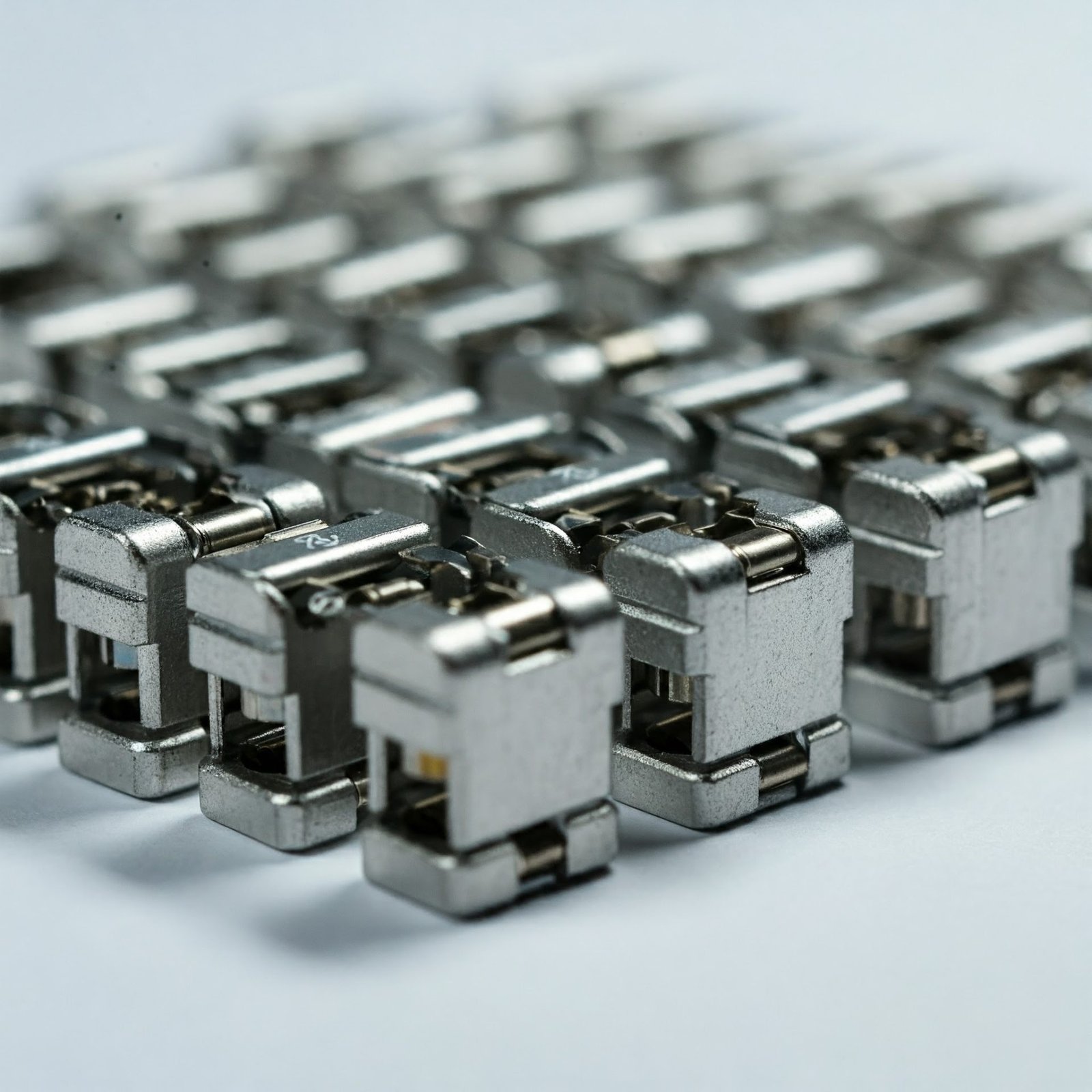
Durable and Precision-Engineered Aluminium Mechanical Splices Connectors

Our aluminium mechanical splices connectors are designed to provide secure and efficient electrical connections, ensuring superior performance and durability.

High-quality aluminium mechanical splices connectors, crafted for efficient electrical connections, offering excellent conductivity and reliability.

At Conex Aluminium Components, we manufacture precision-engineered aluminium mechanical splices connectors that cater to power distribution and electrical systems. These connectors ensure secure and efficient conductor splicing, providing excellent conductivity and corrosion resistance. Ideal for industrial, commercial, and utility applications, our splices connectors are designed for easy installation and long-term reliability. Available in various sizes and configurations, we also offer customized solutions tailored to meet specific project requirements.

Use only the materials listed for the product. Aluminium splices may be intended for aluminium conductors, while dual-rated or bimetallic designs can accommodate specified copper-to-aluminium combinations with suitable plating, separators and oxide control.

Set-screw splices require tightening to a published torque using a calibrated wrench. Shear-bolt connectors use engineered break-off heads to deliver a controlled clamping level across a defined cable range, but the specified bolt sequence must still be followed.

Each conductor must reach the designed stop or insertion mark so current and clamping loads are shared over the intended barrel length. Poor centering can leave insufficient engagement on one side, obstruct insulation rebuilding or create a localized hot spot.

De-energize and verify the cable, cut ends square, strip to the specified length and protect strands from nicks or contamination. Clean aluminium with an approved brush, apply compatible inhibitor where required, and insert each cable immediately after preparation.

Follow the exact connector instructions; multi-bolt designs commonly require staged tightening in a defined order to distribute pressure evenly. Use the stated torque or shear sequence and never substitute bolt grades, reuse shear heads or guess the setting.

Only a splice explicitly approved for the conductor combination should be used. A suitable transition design may incorporate plating, barriers, controlled contact geometry and compatible inhibitor to limit galvanic corrosion and differential thermal movement.

The completed joint must be rebuilt with a cable-accessory system matched to voltage, insulation type, conductor screen, environmental sealing and installation method. Heat-shrink, cold-shrink, resin or molded systems must provide the required dielectric strength, stress control and moisture protection.

Do not assume an electrical splice is a load-bearing fitting. Pull-out performance is product- and conductor-specific, so cable supports should prevent sustained tension, bending and vibration unless the connector is tested and rated for those mechanical duties.

Only when the connector is qualified for the relevant strand class. Fine strands may require purpose-designed inserts or sleeves to distribute bolt pressure; unapproved ferrules can change contact resistance and invalidate the connector rating.

Common causes include wrong size, incomplete insertion, oxidized or dirty strands, missing inhibitor, incorrect bolt sequence, insufficient torque, strand damage and poor insulation sealing. These reduce contact area or clamping stability and can raise joint resistance during load cycles.

Quality controls may include dimensional and material checks, bolt or shear-head verification, conductor pull-out, electrical resistance and heat-cycle testing, subject to the agreed standard. Field inspection can add torque records, visual checks and infrared thermography after energization.

Provide both conductor materials, cross-sections, diameters and strand classes; voltage and current context; cable insulation and joint kit; installation environment; set-screw or shear-bolt preference; standard, testing, certification and quantity. Drawings or samples help Conex review bore geometry, inserts and hardware.