

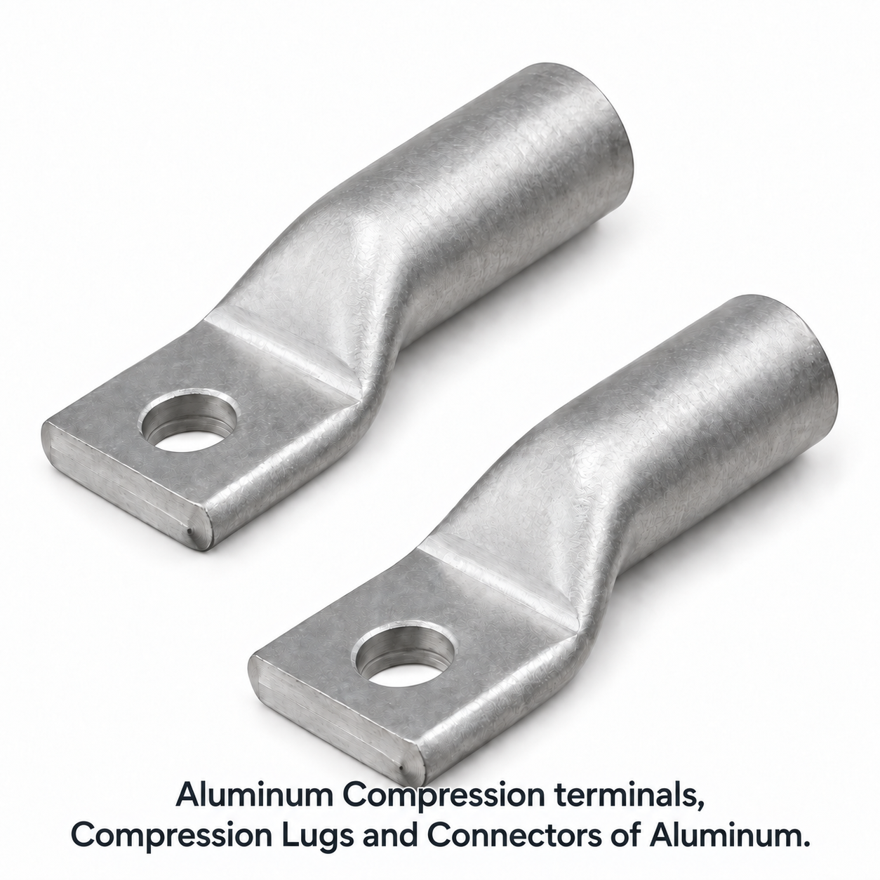
Durable and Precision-Engineered Aluminium Compression Terminals Connectors
Our aluminium compression terminals connectors are designed for secure and efficient electrical connections, ensuring excellent performance and long-lasting reliability.
High-quality aluminium compression terminals connectors for secure and reliable electrical connections in industrial, commercial, and utility applications.
At Conex Aluminium Components, we manufacture premium aluminium compression terminals connectors that cater to diverse electrical systems. These connectors are designed to provide strong mechanical connections and superior conductivity. Ideal for power distribution, switchgear, and control panels, they ensure reliable performance in high-demand environments. Our connectors are available in various sizes and configurations to meet specific application needs. With a focus on quality and customization, Conex offers tailored solutions to ensure maximum efficiency and safety.
Aluminium Compression Terminal Wire Sizes and Stud-Hole Options
Aluminium compression terminals can be engineered for IEC metric conductors and North American AWG or kcmil conductors. Correct selection starts with the conductor material, nominal size, strand construction and actual outside diameter; the terminal barrel, crimp die and number of crimps must be approved as one system.
Wire-size reference: AWG/kcmil and mm²
AWG/kcmil and mm² are different sizing systems and do not have exact one-to-one equivalents. The table gives commonly paired nominal sizes for preliminary selection. Final compatibility must be checked against the conductor standard, stranding class and dimensional data.
| Metric conductor size | Closest common AWG/kcmil size |
|---|---|
| 6 mm² | 10 AWG |
| 10 mm² | 8 AWG |
| 16 mm² | 6 AWG |
| 25 mm² | 4 AWG |
| 35 mm² | 2 AWG |
| 50 mm² | 1/0 AWG |
| 70 mm² | 2/0 AWG |
| 95 mm² | 3/0 AWG |
| 120 mm² | 250 kcmil |
| 150 mm² | 300 kcmil |
| 240 mm² | 500 kcmil |
| 300 mm² | 600 kcmil |
| 400 mm² | 800 kcmil |
| 500 mm² | 1000 kcmil |
Common palm stud-hole options
One-hole and two-hole terminal palms can be produced for metric or inch fasteners. The dimensions below identify the nominal stud or bolt size, not the final machined clearance-hole diameter.
| Metric stud option | Closest common inch stud option | Nominal stud diameter |
|---|---|---|
| M6 | 1/4 in | 6.4 mm / 0.250 in |
| M8 | 5/16 in | 7.9 mm / 0.313 in |
| M10 | 3/8 in | 9.5 mm / 0.375 in |
| M12 | 1/2 in | 12.7 mm / 0.500 in |
| M16 | 5/8 in | 15.9 mm / 0.625 in |
| M20 | 3/4 in | 19.1 mm / 0.750 in |
Information required to select or quote a terminal
- Conductor material, standard, nominal AWG/kcmil or mm² size, strand class and outside diameter.
- One-hole or two-hole palm, finished hole diameter, hole spacing, palm width and terminal angle.
- Operating current, short-circuit duty, voltage class, temperature rating and installation environment.
- Required plating, oxide-inhibiting compound, sealing, identification and applicable approval standard.
- Crimping tool, die profile, die index and required installation or qualification tests.
Need Aluminium Compression Terminals Connectors? Get a Fast, Detailed Quotation
Send your drawing (STEP, IGES, DWG, DXF or PDF) with material grade, finish and quantity. Our engineers reply with a DFM review, price and lead time. MOQ 10 pcs • ISO 9001:2015 • Exports to USA, UK, Europe, Canada & Australia.
Aluminium compression terminals terminate compatible aluminium conductors onto busbars, switchgear, transformers, panels and electrical equipment. A calibrated crimping system deforms the barrel around the conductor to create mechanical retention and a low-resistance path. The terminal must match conductor material, size, construction, current duty, palm interface and applicable standard.
Compatibility depends on conductor metal, cross-sectional area, strand construction, compactness and outside diameter. A terminal approved for one conductor family should not be assumed suitable for another. Provide the conductor standard and manufacturer data so barrel bore, insertion depth, joint compound and crimp schedule can be selected correctly.
Select by the conductor’s verified material, construction and cross-section together with the equipment-pad requirement. Barrel size, palm width, stud-hole diameter, hole spacing, angle and overall length must suit the installation. Cable insulation diameter and bend radius also affect access and clearance. Final selection should follow the approved terminal and crimping chart.
The die profile and size control compression geometry, contact pressure and conductor retention. An incorrect die can under-crimp, damage strands, split the barrel or create excessive resistance. Use the manufacturer-approved tool, die code, number of crimps, sequence and orientation. Tool calibration and maintenance are essential for repeatable joints.
The required quantity and location depend on barrel length, conductor size, connector design and die system. Follow the terminal’s approved crimp schedule and markings rather than using a generic number. Crimps should be applied in the specified direction and spacing to avoid trapping air, displacing compound incorrectly or leaving an uncompressed zone.
Follow the approved installation procedure. Strip insulation to the specified length without nicking strands, verify full conductor insertion, and clean the contact area where required. Aluminium oxide is non-conductive, so an approved oxide-inhibiting compound may be specified. Prepared strands should remain uncontaminated and be inserted promptly.
Approved joint compound helps exclude moisture, limit oxidation and improve long-term interface stability. Some aluminium terminals are supplied pre-filled and sealed. The correct compound must be compatible with conductor and service conditions; excess, substitution or omission can affect the crimp. Follow product instructions for cleaning, filling and storage.
Performance depends on conductive cross-section, crimp quality, interface resistance, palm contact and thermal stability. Qualification may include resistance, temperature-rise, current-cycle and short-circuit tests to the applicable standard. Installation quality remains critical because wrong dies, incomplete insertion, contamination or loose palm bolts can cause local heating.
Direct aluminium-to-copper contact can create galvanic corrosion, especially in moist environments. Use a terminal and interface arrangement specifically approved for the transition, such as a bimetallic palm or suitable plating and protection. The busbar material, hardware, joint compound, environment and torque procedure should be reviewed as one system.
Contact faces must be clean, flat, aligned and protected as specified. Use compatible bolts, washers and the approved tightening torque and sequence. The cable should not impose excessive bending load on the palm. Joint resistance depends on contact pressure, so hardware, lubrication and re-torque requirements must follow the equipment or utility standard.
They can be used outdoors when the terminal, transition interface, sealing, hardware and cable system suit the environment. Moisture, salt and pollution increase corrosion risk. Heat-shrink, boots, joint compound, plated or bimetallic palms and compatible fasteners may be required. Environmental and voltage-clearance requirements should be defined before selection.
Crimped terminals are permanently deformed and should not be reused. If a termination is removed, install a new correctly sized terminal and inspect the conductor for strand damage, oxidation or insufficient remaining length. Crimping tools and dies may be reused only when clean, undamaged, calibrated and approved for the replacement terminal.
Inspection can include material and dimensional checks, barrel bore, palm geometry, stud holes, surface condition, compound fill and markings. Finished joints are checked for conductor insertion, correct die impressions, crimp count, absence of cracks and proper palm bolting. Pull, resistance, thermal-cycle and short-circuit tests may be required for qualification.
Yes. Custom options can include barrel size and length, palm width, angle, stud-hole pattern, inspection windows, sealing, plating, compound and identification. Conex requires conductor specifications, equipment interface, current and fault duty, voltage class, environment, crimp system, applicable standard, tests and quantity to review the design.
Provide conductor material, standard, construction, cross-section and diameter; equipment-pad drawing; current and fault duty; voltage class; palm hole pattern; crimp tool and die system; environment; compound, plating and sealing requirements; tests, certificates, markings, packaging and quantity. Complete conductor data is essential for a reliable match.


