

Aluminum Compression Lugs for Transformers
Aluminum Compression Lugs for Transformers
Aluminum Compression Lugs for Transformers
Transformer connections carry high current through a compact interface, making the cable lug a small component with a major effect on reliability. Aluminum compression lugs for transformers provide a lightweight, economical termination for compatible aluminum conductors when the connector, crimp system and equipment terminal are correctly matched.
This guide covers construction, material compatibility, sizing, crimping, inspection, testing and procurement for utilities, transformer manufacturers, panel builders, EPC contractors and maintenance teams.
What Is an Aluminum Compression Lug?
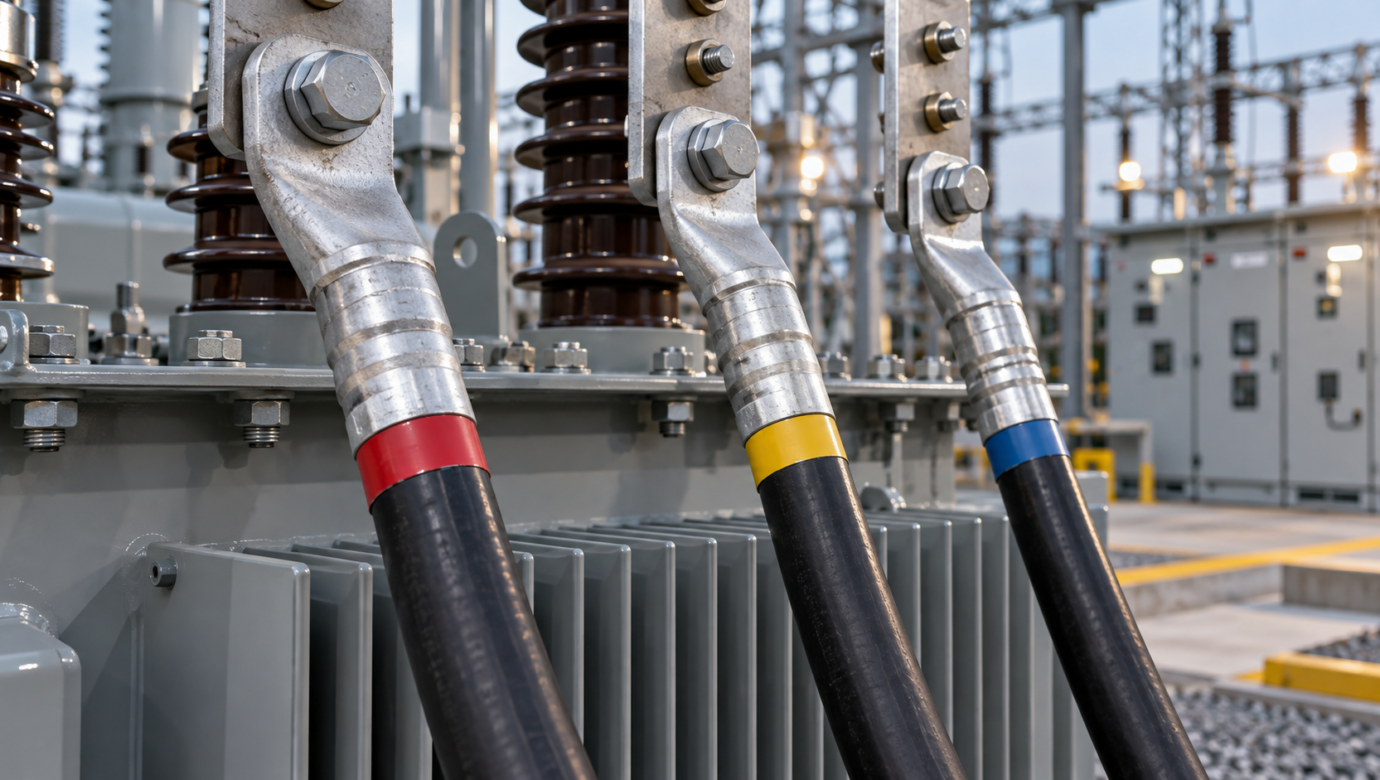
A compression lug converts a stranded cable into a bolted palm connection. The conductor enters a tubular barrel, and a calibrated crimping tool plastically deforms the barrel around the strands. The palm is then bolted to a transformer terminal, busbar or equipment pad. Common designs include one-hole and two-hole palms, straight or angled palms, long and standard barrels, inspection windows and sealed or inhibited barrels.
Why Transformers Need a Carefully Engineered Termination
Transformer lugs experience continuous load current, fault forces, thermal cycling and vibration. A joint with excessive resistance generates heat, which can accelerate oxidation, relax hardware and damage insulation. Reliable performance therefore depends on the complete connection system: cable, lug alloy, barrel preparation, die, tool, number and position of crimps, palm finish, bolts, washers, mating pad and tightening procedure.
Benefits of Aluminum Compression Lugs
- Compatibility with widely used aluminum power cables
- Lower weight than equivalent copper terminations
- Competitive installed cost
- Good conductivity when correctly sized
- Availability in broad conductor and palm configurations
- Options for bi-metallic interfaces where an aluminum conductor meets copper equipment
Conductor Compatibility
Never select a lug by nominal cable size alone. Confirm conductor metal, stranding class, compact or compressed construction, actual diameter and applicable cable standard. A barrel developed for one conductor construction may not compact another properly. Manufacturers should publish or approve the conductor range and matching die system.
Aluminum-to-Aluminum and Aluminum-to-Copper Interfaces
An aluminum palm on an aluminum terminal is generally compatible when surfaces are prepared and protected as specified. Where the equipment pad is copper, a rated bi-metallic lug, plated palm or approved transition method may be required. Direct dissimilar-metal contact in the presence of moisture can drive galvanic corrosion. The equipment manufacturer and connector instructions should govern the final arrangement.
Important Lug Design Features
Barrel length
Long barrels can accommodate multiple crimps and distribute mechanical load, while standard barrels may suit restricted spaces. Use the crimp sequence specified for the exact product.
Palm geometry
Hole size, spacing, palm width, thickness and angle must align with the transformer pad without forcing the cable. Two-hole palms help resist rotation.
Inspection window
A window can confirm conductor insertion, but sealed designs may be preferred in some environments.
Oxide inhibitor
Many aluminum lugs are supplied with compatible joint compound and a plug or cap. Preserve it during storage and installation.
Marking
Durable markings should identify cable range, die reference and manufacturer or traceability code as required.
How Compression Creates the Electrical Joint
The correct die and tool compress the barrel and conductor strands into intimate contact, displacing surface films and reducing voids. Too little compression can leave a resistive, mechanically weak joint. Excessive or incorrect compression can crack the barrel, damage strands or produce sharp flash. Tool calibration and die identification are therefore essential process controls.
Installation Procedure
- Isolate, test and ground equipment according to the approved safety procedure.
- Verify cable, lug, die and tool references.
- Cut the cable squarely without crushing strands.
- Strip insulation to the specified length without nicking conductor strands.
- Clean or brush the conductor when the approved procedure requires it.
- Preserve or apply the specified inhibitor.
- Insert the conductor fully into the barrel.
- Crimp in the marked sequence using the approved calibrated tool.
- Inspect each crimp and remove only permitted flash.
- Prepare the mating pad, align the palm and install specified hardware.
- Tighten bolts to the equipment or connector manufacturer’s value.
- Apply insulation, sealing and phase identification as required.
Common Installation Errors
- Wrong lug for conductor material or strand class
- Mixing dies and lugs from unapproved systems
- Incomplete insertion or incorrect strip length
- Missing, overlapping or misplaced crimps
- Removing strands to make a cable fit
- Bending the palm or cable to correct misalignment
- Using an aluminum palm directly on copper without an approved transition
- Incorrect bolt torque or unsuitable washers
- Allowing water or contamination into the barrel
Inspection and Testing
Visual inspection should verify lug marking, cable insertion, crimp count and position, absence of cracks, correct palm alignment and finished insulation. Commissioning programmes may include torque verification, micro-ohm comparison or thermographic baseline checks. In service, infrared surveys can reveal abnormal temperature rise, but readings should be compared at similar load and environmental conditions.
Specifying Lugs for a Transformer Project
Provide conductor standard, material, size and stranding; transformer terminal material and hole pattern; continuous and short-circuit requirements; barrel style; environmental exposure; plating or transition needs; required tool and die references; applicable standards; testing; marking; packaging and quantity. A drawing of the installation envelope helps avoid cable-bend and clearance problems.
Frequently Asked Questions
1. Can aluminum lugs be used on copper cable?
Only if the lug is explicitly rated for copper or dual-rated service.
2. Can an aluminum lug bolt directly to a copper busbar?
Use a connector or transition method approved for the dissimilar-metal interface.
3. Why is oxide inhibitor used?
It helps disrupt oxide films and exclude moisture from the aluminum joint.
4. Is cable size enough to select a lug?
No. Conductor construction, diameter, material, standard and terminal geometry also matter.
5. What is a bi-metallic lug?
It is engineered to connect an aluminum conductor to a copper contact interface while controlling the transition between metals.
6. Why use a two-hole palm?
Two bolts resist rotation and can improve mechanical stability on suitable equipment pads.
7. Can different brands of dies and lugs be mixed?
Only when the combination is specifically approved; otherwise the achieved compression is uncertain.
8. What does a long barrel provide?
It permits additional crimp length and may improve pull-out and electrical performance where required.
9. Should strands ever be removed?
No. Removing strands changes the conductor area and invalidates the intended connection.
10. What causes a hot transformer lug?
Possible causes include poor crimping, contamination, incorrect sizing, loose bolting, corrosion or overload.
11. How is bolt torque selected?
Use the value specified by the transformer or connector manufacturer for the exact hardware arrangement.
12. Can a compressed lug be reused?
No. Compression lugs are generally single-use components.
13. What markings should be present?
Common markings identify conductor range, die index, manufacturer and traceability information.
14. Are inspection windows always better?
They aid insertion checks, but environmental sealing and project requirements may favour a closed barrel.
15. What information speeds up a quotation?
Send cable details, terminal drawing, required standards, finish, tests, quantity and delivery schedule.
Source Transformer Lugs to Your Specification
Conex Aluminium Components can review custom aluminum lug and electrical-component requirements against buyer drawings and application information. Provide the conductor, palm geometry, finish, testing and quantity for an accurate proposal.
Request a quotation from Conex or review the aluminum products range.